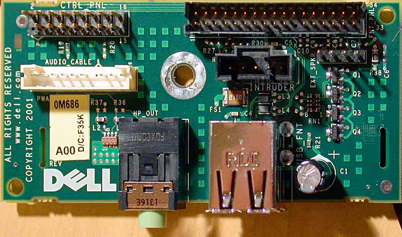
Located halfway up under the front bezel section with the ventilation holes.
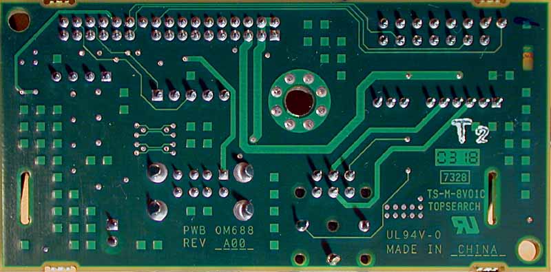
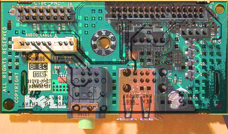
Photo available of the backside and a super-duper overlay and a bigger size front.
See Control Panel documentation.
From the pin-side:
| Pin | Description | Connects to FNT_PNL Pin |
| 1 | Removed and blocked on the connector | — |
| 2 | PWR SWITCH LEFT SIDE (Both) | 20 |
| 3 | GND | GND |
| 4 | HDD LED NEG | 22 |
| 5 | PWR LED GREEN POS | 23 |
| 6 | HDD LED POS | 5 thru R19 |
| 7 | GND | GND |
| 8 | ESUP SWITCH RIGHT SIDE (Both) | 28 |
| 9 | PWR LED YELLOW POS | 27 |
| 10 | N/C | — |
| 11 | GND | GND |
| 12 | N/C | — |
| 13 | ESUP LED NEG | 24 |
| 14 | ESUP LED POS | 5 Thru R20 |
| 15 | GND | GND |
| 16 | GND | GND |
From the pin-side:
| Pin | Description | Connects to |
| 1 | INTRUDER 3 | INTRUDER 3, FNT 32 |
| 2 | VCC ?? | FNT 3, FNT 4 |
| 3 | VCC ?? | FNT 2, FNT 4 |
| 4 | VCC ?? | FNT 2, FNT 3 |
| 5 | LED VCC | CTRL 6 thru R19, CTRL14 thru R20 |
| 6 | ? | |
| 7 | ? | |
| 8 | INTRUDER 5 | INTRUDER 5 |
| 9 | GND | GND |
| 10 | GND? | GND? |
| 11 | GND | GND |
| 12 | ? | |
| 13 | ? | |
| 14 | GND | GND |
| 15 | ? | |
| 16 | GND | GND |
| 17 | ? | |
| 18 | ? | |
| 19 | GND | GND |
| 20 | PWR SWITCH LEFT SIDE (Both) | CTRL 2 |
| 21 | Pin removed | — |
| 22 | HDD LED NEG | CTRL 4 |
| 23 | PWR LED GREEN POS | CTRL 5 |
| 24 | ESUP LED NEG | CTRL 13 |
| 25 | GND | GND |
| 26 | ? | |
| 27 | PWR LED YELLOW POS | CTRL 9 |
| 28 | ESUP SWITCH RIGHT SIDE (Both) | CTRL 8 |
| 29 | GND | GND |
| 30 | INTRUDER 1 | INTRUDER 1 |
| 31 | EXT_SPK 2 | EXT_SPK 2 |
| 32 | INTRUDER 3 | INTRUDER 3 |
| 33 | EXT_SPK 4 | EXT_SPK 4 |
| 34 | EXT_SPK 1 | EXT_SPK 1 |
From pin-side:
![]()
| Pin | Description | Connects to |
| 1 | GND | GND |
| 2 | OUT LEFT | 3.5 jack tip |
| 3 | GND | GND |
| 4 | OUT RIGHT | 3.5 middle ring |
| 5 | GND | GND |
| 6 | ? | |
| 7 | Pin removed | — |
| 8 | ? | |
| 9 | ? | |
| 10 | GND | GND |
From pin-side:
![]()
| Pin | Description | Connects to |
| 1 | FNT 30 | |
| 2 | GND | GND |
| 3 | FNT 1, FNT 30 | |
| 4 | GND | GND |
| 5 | FNT 8 |
From pin-side:
![]()
| Pin | Description | Connects to |
| 1 | FNT 34 | |
| 2 | FNT 31 | |
| 3 | GND | GND |
| 4 | FNT 33 |
From solder-side:
When unconnected to a 3.5 jack:
When connected to a jack:
| Pin | Description | Connects to |
| 1 | SENSE | GND if connected, otherwise Base Ring (floats) |
| 2 | GND | GND |
| 3 | SENSE | GND if unconnected, otherwise floats |
| 4 | SENSE | GND if connected, otherwise Base Ring (floats) |
| 5 | GND | GND |
| 6 | SENSE | GND if unconnected, otherwise floats |
| 7 | Left channel | Tip |
| 8 | GND if connected, otherwise floats | Base Ring |
| 9 | Right channel | Middle Ring |
This I cannot be bothered with, way too many surface mounted components. You are welcome to drop me an email (@ 400sc-at-peterlada-dot-com) if you draw a circuit diagram, or have any info.